TRIKE FRAMES-ONWARDS & UPWARDS. PART 4.
Home / Forum / Pictures / Bikes / Trikes / HotRods

Page 1
Page 2
Page3
Page 4
Page 5
Page 6
Page 7
 

TRIKE FRAMES-ONWARDS & UPWARDS. PART 4.
(Click on pictures for larger images)

Hi. Come on in. Glad you came back. I’d feel stupid just typing this to myself.
Right-o then, let’s get cracking.
Last time you were here we’d set all the running gear for our trike out on the garage floor, propped the complete front end up in place to determine the height of the headstock from the ground & the angle of the forks, then we bent a pair of tubes to form the down tubes, running back under the engine to meet the back axle. So we’ve got the bottom cradle of our frame tack-welded together. The engine is sat on it’s front mounts, which we made several chapters ago, (hope you were paying

Click on picture for larger image
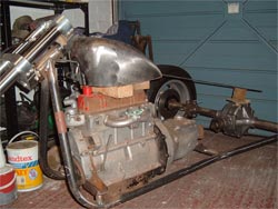
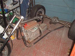
attention). Now we need to support the back end of the motor. That’s easy. Check the engine is sitting level with the ground & square within the frame. Take the two gearbox mounts we’ve already made & bolt them to the underside of the ‘box. Cut a length of 1” tube to fit across the frame rails, scalloping the ends to fit snugly over them. Offer it up to the mounts & weld together where they touch. Weld the ends of the tube to the frame on either side, checking with a square that it’s…square, & if all’s well, when you take away whatever you’ve blocked the engine up off the floor with, it should remain suspended in the frame. If it falls to the ground with a clunk, go back a few lines & do the welding bit again. Maybe you forgot to switch the thing on.
   

I’m assuming anybody who actually tries to put this rather sketchy information into practice already knows how to weld, so I won’t bother with advice on correct penetration, (!), wire thickness etc. We use a 150 MIG welder with 0.8 wire & Argonshield gas though.
Alright, what’s next? Top tube? Again, not as difficult as you might think. None of this is really. It’s just a matter of having the confidence to get stuck in. If you mess it up, cut another piece of tube & try again. Because we want the finished trike to look small & lightweight, we’ve opted for a King Sportster petrol tank. This is an off the shelf aftermarket custom tank, loosely based on the Harley Sportster one but a couple of inches wider. With it propped up on top of the motor in roughly

Click on picture for larger image Click on picture for larger image
the right position, we can check there’s enough room for the forks to turn onto full lock, then measure up for the top frame tube. For this we use 1 ½” bore pipe. The tunnel under the tank is just under 2” wide, so we’ve had to shave the sides of our tube a little with Mr Angle Grinder.
   

In the photo you can see we’ve used an old length of flat bar to show the line the top tube will take under the tank. This lets us check we’ll have enough room to get the engine in & out of the finished frame. It also gives us an idea of the angle needed to bring the back end of the tube down behind the engine & how long the tube has to be to accommodate the tank. Out with the angle form we made earlier, set it to the required angle, bend the tube to suit & trim it to length. All’s well so

Click on picture for larger image
we can offer the tube up, scallop the front end around the headstock,then glue it in place with the welder. Easy! A line is taken from the headstock to the centre of the axle diff’ housing to check everything’s square & central. Lookin’ good. Next we need to support the end of that top tube. Back to the 1” pipe again. Two lengths are cut to fit between the end of the top tube & the bottom rails. They’re angled back a little as this will brace the front of the frame better than a vertical tube. The angle is purely personal choice but obviously needs to clear the gearbox casing. In addition, we plan to make up a new gearstick that will come out sideways from under the seat so these tubes have to be placed to allow room for that as well -and you thought we just made this up as we went along!
Click on picture for larger image
A bit of head-scratching, standing back & squinting at it, trying scrap bits of pipe at various angles & drinking tea, then the tubes are cut, scalloped to sit on the bottom rails, notched at the top to fit under the top tube, & welded in place. Hey! Now we’ve got a completed engine cradle! Are we good or what. Have another cup of tea.
Lastly for today, we need to tie the front cradle to the axle. More 1” tube. We chose to run it from the point where the previous tubes meet the top one, straight back to the axle clamps. This just happens to give us enough room beneath the seat for our proposed gearstick set-up & more importantly, looks good!
   
O.K, that’s about it for today. We’ve built the basic structure &, personally, I think it’s not looking bad at all. Next time we’ll run a tube across the back end to tie the two axle clamps together & have a look at the seat frame & footpegs. These ramblings aren’t really intended as a step by step guide to frame building though. As I’ve already said, everyone has their own ideas of how it should be done, but hopefully it’ll show what can be achieved with basic tools & facilities, (Nigel, your garage isn’t a glorified cupboard really, it’s very nice -honest!), & a bit of common sense.
Ya all come back now, y’ hear.