TRIKE FRAMES-THE BENDY BITS. PART 3.
Home / Forum / Pictures / Bikes / Trikes / HotRods

Page 1
Page 2
Page3
Page 4
Page 5
Page 6
Page 7


TRIKE FRAMES-THE BENDY BITS. PART 3.

O.K, we’re back in the on-line Manky Monkey Motors Tricycle Emporium.
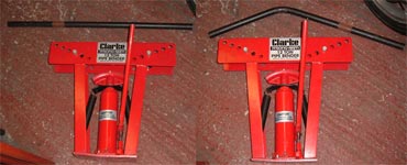
Haven’t been here for several weeks & a few people have been asking me questions, so I guess it’s about time we started bending some tubes. Well there’s the pipe bender, there’s a stack of tubing -away you go. What? You don’t know where to start? You think I Know what I’m doing? I’m a Postman remember, not an engineer. Alright, I’ll try & show you how this particular frame was put together, but I’m sure other people would use alternative methods & come up with different ideas. That’s the beauty of custom building though. Every machine is individual & is an expression of the tastes & talents of the builder. Not sure how much of either commodity I possess, but, personally, I like very minimal, low-tech designs. Simple & functional, that’s me!
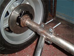
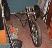
Right, let’s see. Where did we get to? Oh yeah, we’ve laid the various components out on the garage floor & moved ‘em around, sitting them on blocks of wood, paint tins etc to achieve the desired height. Once we’re happy that everything looks right -the proportions are O.K, there’s enough room to fit everything in within our imaginary frame, including the rider & pillion, plenty of ground clearance etc, we can take a few basic measurements & get it all square & symmetrical. Won’t bore you too much with that, except to say it really is worth spending time to get it right. A few hours endlessly re-checking everything with a tape measure, steel rule, spirit level & square is definitely worth it in the long run. At the end of the day, as long as the headstock is level, (we use a simple plumb-bob to ensure it sits right), & the rear axle is at 90 degrees to it, the finished trike should run true, without crabbing off to one side & ending up in the gutter. We measure from a central point on the engine, (on Reliants there’s a casting seam that runs up the middle of the gear-box bell-housing. Cant use the cylinder head or rocker cover as they’re off-set to one side), to the centre of the axle diff housing. From the ends of the axle tubes to the centre line of the engine. We line up the centre-line of the headstock with the centre line of the motor, using the crankshaft pulley bolt as a reference, then measure from there back to both sides of the axle etc, etc. Everything is measured, shuffled about, measured again, checked with the measurements from the opposite side of the frame -well, you get the idea. We work directly off the concrete garage floor as we’ve already satisfied ourselves it’s as level as any work bench we could knock up. Reference marks are drawn in case anything gets accidentally moved.
So, pass me a length of that tubing will you. The 1” bore stuff leant against the wall over there.
This comes in 20 foot lengths -or whatever the metric equivalent of that is, but our local supplier chops it in half on request to make it easier to get home. At roughly a quid a foot, it’s not the end of the World if we make a mistake so don’t be

Click Picture For Larger Image
afraid to get stuck in. First off, we need to support the headstock, We’ve decided it looks best at roughly 45 degrees. That will give us plenty of straight line stability without making the steering so heavy we can’t manoeuvre it at slow speeds. The front down tubes are vertical as we intend to hang the radiator on these so we need to put matching 90 degree bends in two lengths of tube. If you’ve never seen a hydraulic pipe bender before, there should be a photo hereabouts.
   
It’s a very simple machine. We bought ours new for about 85 quid. A glorified hydraulic bottle jack with a curved former on the end, sitting in a framework that supports a pair of rollers. The forming heads are interchangeable for different sizes of tube & the rollers can be moved to vary the tightness of the bend. Simply lay the tube into the former, pump up the handle & as the tube is pushed against the rollers it creates a bend. The trick is in making matched pairs of bends. For this we use an angle-form. Two flat metal straps held together at one end with a nut & bolt which can be set at the desired angle then checked against the tube as you bend it. The tube tends to spring back slightly as it’s released from the bender so we allow for that with an extra couple of pumps on the handle. A little practice on a spare piece of tube & you’ll soon get the hang of it.
So we’ve measured from the headstock down to the engine mount, allowed a couple of inches extra, & bent the tube. A little of the length is lost in creating the bend but this varies depending on the diameter of tube used & the tightness of the bend. Always better to cut a tube too long than bend it & find it’s half an inch too short. On our frame the centre-line of the down tubes sits 4” in front of the engine mounts to give room for the electric radiator fan we’ll be using. We know the height of the headstock from the ground, so we can lay the two bent tubes along under the motor, blocking them up off the floor to the right height & set them at the right width to line up with the engine mounts. The vertical down tubes can then be angled inwards to meet the headstock. A little work with an angle grinder & a file & the ends are scalloped to fit neatly around the headstock tube. This is one of the most important joints on the whole frame so we’re very careful to ensure the down tubes are symmetrical & that the headstock sits square & along the centre-line of the engine. Difficult to explain.
Meanwhile, at the back end, we’ve bolted the axle clamps we made last time around the axle an equal distance in from the
Click Picture For Larger Image
hubs & checked the mating face between the two halves of the clamps sits vertically. Now we need to put a second bend in each frame tube to bring them up to meet the clamps. In our case the tube needs to kick out by about 6” & up by around 4 or 5”. No easy way to explain this either, but it took us several hours of gentle bending, trying in place, head scratching, bending a little more & so on, to get it right. Even then we had to heat the second tube with a blow lamp & tweak it slightly to get it to perfectly match the first.
Once that was done, the ends of the tubes were scalloped to fit against the back of the clamps then tack-welded in place, (a small, temporary weld just to hold them in position).
 
Click Picture For Larger Image
With the engine mounts we made earlier bolted to the motor & sitting on the frame tubes the headstock is laid back in place, measured, double-checked, tack-welded & checked again.
So now we can carefully slide the front end into the headstock & we’ve got all three wheels tied together, giving us a rigid base from which to start building our frame.
This has all got a bit complicated & wordy but hopefully the photos explain it a little more. We use very basic methods but take plenty of time to ensure the results are as accurate as possible. Three of us have checked every frame dimension in every direction & can honestly say it’s spot on. I’d be happy for anyone to run a spirit level & tape measure over it. And the frame.
 
Alright, next time we’ll sort out the gear-box mounts & start building upwards from our bottom rails. I’m hungry after all that. Anyone remember to bring some cake?